· 17 min read
I turned a simple gate opener into a smart device with Home Assistant
After installing an automatic gate opener I greatly enhanced its functionality by having my first foray into ESP32 boards. I wired up relays, octocouplers, and created my first firmware to have full control over my gate from my phone.
The goal
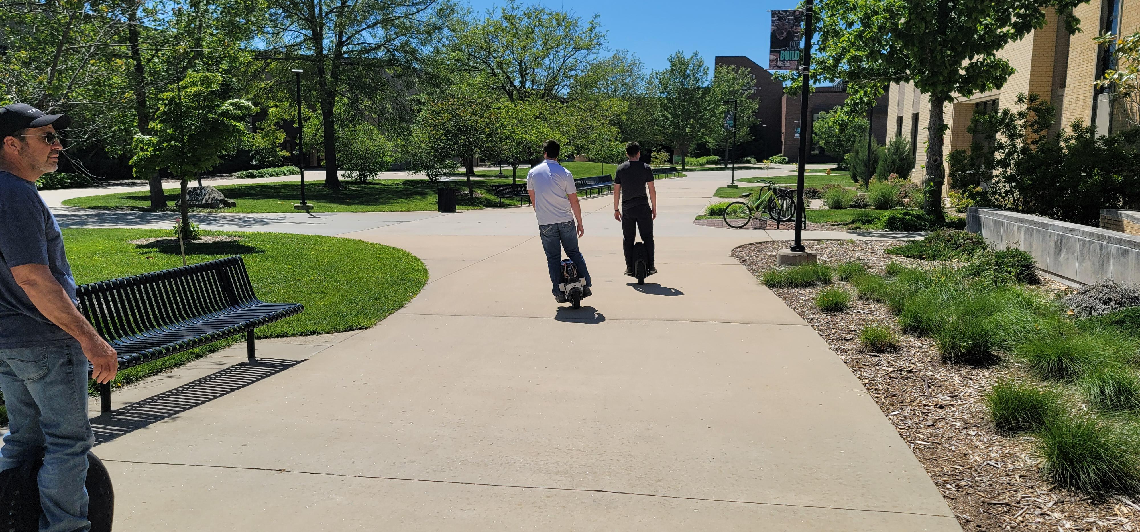
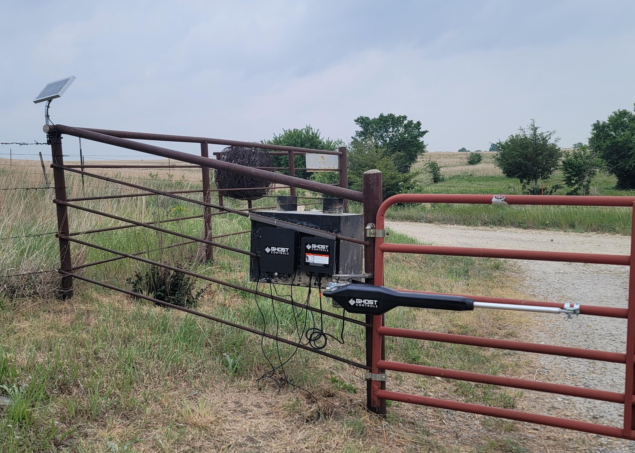
In a continous effort to analyze and improve QoL efforts it was decided that an automatic gate opener would be a good investment. Ghost Controls has a simple DIY kit that filled the needs. The kit allowed for three ways to open the gate. From a remote, from the keypad, or from a buried induction sensor. All of these work if you’re within 30-50 feet, but what happens if you wanted to open it from your house that is a couple hundred feet away? Or better yet, what if you wanted to be notified every time the gate was opened? You could purchase Ghost Control’s Smart Gate Pacakge for $275 and extend the range slightly further for bluetooth and wifi (~200ft). You would then need to download an app, and control the devices from there. This upgrade would also necessitate buying the larger 30w solar system and a deep cycle marine battery, or I could give up on being able to remotely control the gate and only be notified through an alarm in the house buy purchasing something similar to a Dakota Alert for ~$300. Either option far exceeds my $150 budget.
Lets face it. It doesn’t take a genius to understand there are better solutions. I want scheduling, live status and notifications on both my phone and with a speaker inside my house. Two ChatGPT prompts later I had learned about ESP32 boards, LoRa antennas, relays, and octocouplers. From there, the goal was to connect two LoRa boards, one at the gate sipping off of the lead-acid batteries, sensing the status of the gate and wired up to open it, and another ESP32 board in my house connected to Home Assistant that would allow me to monitor, schedule, and automate away to my hearts content.
For background information, prior to this my exposure to ESP32 boards was a Feather M0 project for a DIY 3D printed open-source CAD mouse (A project that never got to the point of using the Feather)
Planning
All plans are simple when you don’t understand the complexity. This is one of the few projects that truly stayed simple throughout, and has spawned a love and appreciation for this class of electronics.
Due to my lack of expertise the plan was to first educate myself on the subject of Home Assistant and ESPHome integrations, as well as flashing firmware, and double checking ChatGPT’s work on LoRa antennas. From there I could create a BOM, determine software specs and application needs, write the C++ firmware with the help of PlatformIO, and then define everything on the house-side board with YAML in ESPHome. At that point all functions should be exposed to Home Assistant, and automations and controls can be created.
- Educate myself
- Bill Of Materials
- Software Specs
- Write, build, flash firmware (gate-side)
- Write, build, flash firmware (house-side)
- Install
- Automate
Education
I prefer learning through iteration. I find it to be the fastest format for learning when you immerse yourself in a project, attempt to apply what you’ve learned, fail, and learn how to fix it. With that my education taught me that to build firmware for these devices I would need a framework. Many people use Arduino, but some use PlatformIO. PlatformIO seems to be more universal, and integrates well with VS Code. My preliminary education also confirmed that the LoRa setup would more than exceed my distance needs. I then described what I intended to monitor and control to ChatGPT, where it created a short BOM.
Bill Of Materials
I chose the Heltec WiFi LoRa V4 board for my application. I then purchased a 3.3v relay, two octocouplers, and two large magnetic mount antennas.
- Heltec V4($38+$30): this board had the WiFi to talk to Home Assistant, and the LoRa antenna to speak between boards. Looking back, I would not have gone with this board, I would have stuck with the V3, as it has better PlatformIO and ESPHome support.
- 3.3v Relay($13): These were sold in a 5 pack, but I only needed one. Looking back, I also would have skipped getting a speciality 3.3v relay, and utilized a 5v relay. In my preliminary research I did not realize the Heltec board supported it.
- Octocouplers($7): These isolate current from two systems, and allow the board to detect a current change (open/close). I would absolutely buy these again, as they have built in resistors to tolerate a larger voltage range.
- LoRa Antenna($16): These antennas have worked great, however I honestly do not know enough to judge them. My judgement is binary, and they work, so they’re good.
NOTE: I do not have a buck converter in here. This is because I did not do enough research, and instead chose to fry the gate board hooking up the battery wires to a 12v system. If replicating this, get a buck converter. They’re cheap and will save you $30 in a fried board.
In total this BOM costs $104. After the buck converters ($15) the total is $119. After frying the first board the total is $149.
With the parts purchased I spent their transit time writing the firmware and preparing my Home Assistant instance.
Software Specs
Before touching a line of code I specd out what I wanted to happen. I wanted to ensure that in the future if I expanded my ESP boards I would have a proper syntax to use network wide. I wanted to ensure that all transmissions were reliable, and I would know when they were not, and I wanted to use the screen to quickly debug failure points.
- Creating a naming convention
- Ensure network reliability
- Quick triaging with screen
Without overthinking the naming convention I decided to start with something simple {Board_Name}:{Sensor_Name}?:{Sensor_Value}. This would mean that the gate board recieving a trigger that the vehicle sensor had been set off would send Gate_Sensor:Vehicle. This covers outgoing metrics, but does not cover incoming messages. Due to my network reliability requirement I decided all inbound messages would contain {Message_Type}:{Value} so that when the house board recieved anything it would return Received:{Sensor_Name} and when it needed to send a command Command:Open_Gate.
For reliability all external boards will send 5 Sensor_Name:Sensor_Value messages at 1x per second. They should only send one message before receiving their acknowledgement message from the home board. In order to quickly triage where the problem lies each event should display on the screen. Overall this is simple for business specs, but does not cover any technical limitations or implementations needed for this specific board.
Programming the gate-side board
I’ll admit it. I’m a fraud. I didn’t write any code for this. I set up the PlatformIO extension in VS Code, and Claude Opus 4.6 wrote every single line. I needed to assist when I found out that PlatformIO does not natively support the Heltec V4 board. However I use “assit” lightly, as even that Claude walked me through with the help of a simple #fetch https://github.com/paulmarx-dev/Heltec-ESP32-LoRa-V4-on-PlatformIO prompt.
I will let all of you be the judge of the quality of code that it wrote:
// Gate Board Firmware - Heltec WiFi LoRa 32 V3
// Controls: Vehicle sensor (optocoupler), Alarm speaker detection (optocoupler), CYC relay
// Communicates with Lab Board via LoRa (RadioLib SX1262, 915MHz)

#include <Arduino.h>
#include <RadioLib.h>
#include <Wire.h>
#include <SSD1306Wire.h>

// --- OLED Display ---
// Heltec V4 OLED pins
#define OLED_SDA    17
#define OLED_SCL    18
#define OLED_RST    21
SSD1306Wire display(0x3c, OLED_SDA, OLED_SCL, GEOMETRY_128_64);

// Display message buffer (last 4 lines)
#define DISPLAY_LINES 4
String displayLines[DISPLAY_LINES];
int displayLineIdx = 0;

// --- Pin Definitions ---
// Heltec V3 LoRa SX1262 pins (board-defined, do not change)
#define LORA_SCK   9
#define LORA_MISO  11
#define LORA_MOSI  10
#define LORA_NSS   8
#define LORA_RST   12
#define LORA_DIO1  14
#define LORA_BUSY  13

// GPIO for sensors and relay
#define PIN_VEHICLE_SENSOR  5   // Optocoupler input (active LOW on vehicle detect)
#define PIN_ALARM_SPEAKER   6   // Optocoupler input (active LOW on alarm beep)
#define PIN_CYC_RELAY       4   // Relay output (HIGH = energize relay = ground CYC)

// GC1109 RF front-end control (Heltec V4)
#define PIN_RF_CTX          7   // CTX/VFEM - TX control
#define PIN_RF_CSD          2   // CSD - chip select/shutdown
#define PIN_RF_CPS         46   // CPS - power supply control

// --- Configuration ---
#define LORA_FREQUENCY      915.0   // MHz
#define LORA_BANDWIDTH      125.0   // kHz
#define LORA_SPREAD_FACTOR  9
#define LORA_CODING_RATE    7
#define LORA_SYNC_WORD      0x12
#define LORA_TX_POWER       17      // dBm

#define RETRY_INTERVAL_MS   1000
#define MAX_RETRIES         5
#define RELAY_PULSE_MS      620
#define ALARM_DEBOUNCE_MS   4000
#define OPEN_GATE_COOLDOWN_MS 5000

// --- LoRa Radio ---
SPIClass loraSPI(HSPI);
SX1262 radio = new Module(LORA_NSS, LORA_DIO1, LORA_RST, LORA_BUSY, loraSPI);

// --- State ---
unsigned long lastDisplayUpdate = 0;
#define DISPLAY_CLEAR_MS 15000
volatile bool vehicleTriggered = false;
bool alarmActive = false;
unsigned long lastAlarmTrigger = 0;
unsigned long lastOpenGateTime = 0;

// Retry state
enum SensorEvent { NONE, VEHICLE, ALARM };
SensorEvent pendingEvent = NONE;
unsigned long lastRetrySend = 0;
int retryCount = 0;

// --- Forward declarations ---
void handleIncomingCommand(const char* cmd);

// --- OLED Display Helpers ---
void displayInit() {
  // Enable Vext power to OLED (Heltec V3/V4: GPIO 36, active LOW)
  pinMode(36, OUTPUT);
  digitalWrite(36, LOW);
  delay(100);

  pinMode(OLED_RST, OUTPUT);
  digitalWrite(OLED_RST, LOW);
  delay(50);
  digitalWrite(OLED_RST, HIGH);
  delay(50);

  display.init();
  display.flipScreenVertically();
  display.setFont(ArialMT_Plain_10);
  display.clear();
  display.drawString(0, 0, "Gate Board Ready");
  display.display();
}

void displayMessage(const String& msg) {
  // Scroll buffer
  displayLines[displayLineIdx % DISPLAY_LINES] = msg;
  displayLineIdx++;
  lastDisplayUpdate = millis();

  // Redraw
  display.clear();
  display.setFont(ArialMT_Plain_10);
  for (int i = 0; i < DISPLAY_LINES; i++) {
    int idx = (displayLineIdx - DISPLAY_LINES + i);
    if (idx >= 0) {
      display.drawString(0, i * 16, displayLines[idx % DISPLAY_LINES]);
    }
  }
  display.display();
}

// --- ISR for Vehicle Sensor ---
void IRAM_ATTR vehicleSensorISR() {
  vehicleTriggered = true;
}

// --- LoRa Helpers ---
bool loraInit() {
  loraSPI.begin(LORA_SCK, LORA_MISO, LORA_MOSI, LORA_NSS);

  Serial.print("[LoRa] Initializing... ");
  int state = radio.begin(LORA_FREQUENCY, LORA_BANDWIDTH, LORA_SPREAD_FACTOR,
                          LORA_CODING_RATE, LORA_SYNC_WORD, LORA_TX_POWER);
  if (state != RADIOLIB_ERR_NONE) {
    Serial.printf("FAILED (%d)\n", state);
    return false;
  }
  Serial.println("OK");

  // Set DIO2 as RF switch control (required for Heltec V3)
  radio.setDio2AsRfSwitch(true);

  return true;
}

bool loraSend(const char* message) {
  Serial.printf("[LoRa TX] %s\n", message);
  displayMessage(String("TX: ") + message);
  int state = radio.transmit(message);
  if (state != RADIOLIB_ERR_NONE) {
    Serial.printf("[LoRa TX] Failed (%d)\n", state);
    return false;
  }
  return true;
}

// Returns true if a message was received, copies into buffer
bool loraReceive(char* buffer, size_t bufLen, unsigned long timeoutMs) {
  unsigned long start = millis();
  while (millis() - start < timeoutMs) {
    String received;
    int state = radio.receive(received, 0);  // non-blocking with 0 length = check available
    if (state == RADIOLIB_ERR_NONE && received.length() > 0) {
      received.toCharArray(buffer, bufLen);
      Serial.printf("[LoRa RX] %s\n", buffer);
      displayMessage(String("RX: ") + buffer);
      return true;
    }
    delay(10);
  }
  return false;
}

// Send message with retry, listening for expected ACK
bool loraSendWithRetry(const char* message, const char* expectedAck) {
  for (int i = 0; i < MAX_RETRIES; i++) {
    loraSend(message);

    // Listen for ACK for up to 1 second
    char rxBuf[64] = {0};
    if (loraReceive(rxBuf, sizeof(rxBuf), RETRY_INTERVAL_MS)) {
      if (strcmp(rxBuf, expectedAck) == 0) {
        Serial.printf("[ACK] Received: %s\n", expectedAck);
        return true;
      }
      // Check if it's a command while we're waiting
      handleIncomingCommand(rxBuf);
    }
  }
  Serial.printf("[ACK] Gave up after %d retries for: %s\n", MAX_RETRIES, message);
  return false;
}

// --- Relay Control ---
void pulseRelay() {
  Serial.println("[Relay] Pulsing CYC relay for 300ms");
  digitalWrite(PIN_CYC_RELAY, HIGH);
  delay(RELAY_PULSE_MS);
  digitalWrite(PIN_CYC_RELAY, LOW);
}

// --- Command Handler ---
void handleIncomingCommand(const char* cmd) {
  if (strcmp(cmd, "Command:Open_Gate") == 0) {
    unsigned long now = millis();
    if (now - lastOpenGateTime < OPEN_GATE_COOLDOWN_MS) {
      Serial.println("[CMD] Open_Gate ignored (cooldown)");
      return;
    }
    lastOpenGateTime = now;
    pulseRelay();
    loraSend("Received:Open_Gate");
  }
}

// --- Setup ---
void setup() {
  Serial.begin(115200);
  delay(1000);
  Serial.println("\n=== Gate Board Starting ===");

  // Configure GPIO
  pinMode(PIN_VEHICLE_SENSOR, INPUT_PULLUP);
  pinMode(PIN_ALARM_SPEAKER, INPUT_PULLUP);
  pinMode(PIN_CYC_RELAY, OUTPUT);
  digitalWrite(PIN_CYC_RELAY, LOW);

  // Enable GC1109 RF front-end for full TX power
  pinMode(PIN_RF_CTX, OUTPUT);
  digitalWrite(PIN_RF_CTX, HIGH);
  pinMode(PIN_RF_CSD, OUTPUT);
  digitalWrite(PIN_RF_CSD, HIGH);
  pinMode(PIN_RF_CPS, OUTPUT);
  digitalWrite(PIN_RF_CPS, HIGH);

  // Initialize OLED display
  displayInit();

  // Attach vehicle sensor interrupt
  attachInterrupt(digitalPinToInterrupt(PIN_VEHICLE_SENSOR), vehicleSensorISR, FALLING);

  // Initialize LoRa
  if (!loraInit()) {
    Serial.println("[FATAL] LoRa init failed. Halting.");
    while (true) { delay(1000); }
  }

  Serial.println("=== Gate Board Ready ===");
}

// --- Main Loop ---
void loop() {
  // 1. Check vehicle sensor trigger (from ISR)
  if (vehicleTriggered) {
    vehicleTriggered = false;
    Serial.println("[Sensor] Vehicle detected!");
    loraSendWithRetry("Gate_Sensor:Vehicle", "Received:Vehicle");
  }

  // 2. Check alarm speaker (polled with debounce)
  bool alarmPin = (digitalRead(PIN_ALARM_SPEAKER) == LOW);
  if (alarmPin && !alarmActive) {
    unsigned long now = millis();
    if (now - lastAlarmTrigger >= ALARM_DEBOUNCE_MS) {
      lastAlarmTrigger = now;
      alarmActive = true;
      Serial.println("[Sensor] Alarm detected!");
      loraSendWithRetry("Gate_Sensor:Alarm", "Received:Alarm");
      alarmActive = false;
    }
  }
  if (!alarmPin) {
    alarmActive = false;
  }

  // 3. Check for incoming LoRa commands
  char rxBuf[64] = {0};
  if (loraReceive(rxBuf, sizeof(rxBuf), 50)) {
    handleIncomingCommand(rxBuf);
  }

  // 4. Auto-clear display after 15 seconds of inactivity
  if (lastDisplayUpdate > 0 && (millis() - lastDisplayUpdate >= DISPLAY_CLEAR_MS)) {
    display.clear();
    display.display();
    lastDisplayUpdate = 0;
  }
}
At this point the software was ready to flash. I ran pio run -t upload -t monitor and a few seconds later “Gate Board Ready” appeared on the screen.
Programming the house-side board
I am afraid on this front I also did not write a single line. To make matters worse, due to ESPHome and Home Assistant’s robust documentation, I prompted Claude to write the YAML file for me based upon the main.cpp code.
It took me longer to add the ESPHome app into Home Assistant (4 clicks + Install time) than it did for the perfect configuration file to be written. I made one manual edit, which was changing the board name on line 21 from “heltec_wifi_lora_32_V4” to “heltec_wifi_lora_32_V3” as that was the most recognized board, and still compatible with the V4. Since the YAML defined the pinout there is no funcitonal difference.
esphome:
  name: gate-lab-board
  friendly_name: Gate Lab Board
  on_boot:
    - output.turn_on: fem_ctx
    - output.turn_on: fem_csd
    - output.turn_on: fem_cps

output:
  - platform: gpio
    id: fem_ctx
    pin: GPIO7
  - platform: gpio
    id: fem_csd
    pin: GPIO2
  - platform: gpio
    id: fem_cps
    pin: GPIO46

esp32:
  board: heltec_wifi_lora_32_V3
  framework:
    type: arduino

wifi:
  ssid: !secret wifi_ssid
  password: !secret wifi_password

  ap:
    ssid: "Gate-Lab-Fallback"
    password: !secret fallback_password

captive_portal:

logger:
  level: DEBUG

api:
  encryption:
    key: !secret api_key
  services:
    - service: open_gate
      then:
        - script.execute: open_gate_retry

ota:
  - platform: esphome
    password: !secret ota_password

# --- LoRa SX1262 (Heltec V3 pins) ---
spi:
  clk_pin: GPIO9
  mosi_pin: GPIO10
  miso_pin: GPIO11

sx126x:
  id: lora_radio
  cs_pin: GPIO8
  dio1_pin: GPIO14
  rst_pin: GPIO12
  busy_pin: GPIO13
  hw_version: sx1262
  modulation: LORA
  frequency: 915MHz
  bandwidth: 125_0kHz
  spreading_factor: 9
  coding_rate: CR_4_7
  sync_value: [0x14, 0x24]
  pa_power: 17
  rf_switch: true
  tcxo_voltage: 1_8V
  tcxo_delay: 5ms
  crc_enable: true
  rx_start: true
  on_packet:
    then:
      - lambda: |-
          std::string msg(x.begin(), x.end());
          ESP_LOGI("lora", "RX: %s (rssi=%.1f, snr=%.1f)", msg.c_str(), rssi, snr);

          if (msg == "Gate_Sensor:Vehicle") {
            id(gate_vehicle).publish_state(true);
            id(vehicle_auto_off).execute();
            id(send_ack_vehicle).execute();
          } else if (msg == "Gate_Sensor:Alarm") {
            id(gate_alarm).publish_state(true);
            id(alarm_auto_off).execute();
            id(send_ack_alarm).execute();
          } else if (msg == "Received:Open_Gate") {
            id(open_gate_pending) = false;
            ESP_LOGI("lora", "Open_Gate ACK received");
          }

# --- Globals for retry state ---
globals:
  - id: open_gate_pending
    type: bool
    initial_value: 'false'
  - id: open_gate_retries
    type: int
    initial_value: '0'

# --- Scripts ---
script:
  # Send ACKs
  - id: send_ack_vehicle
    then:
      - sx126x.send_packet:
          data: !lambda |-
            std::string msg = "Received:Vehicle";
            return std::vector<uint8_t>(msg.begin(), msg.end());

  - id: send_ack_alarm
    then:
      - sx126x.send_packet:
          data: !lambda |-
            std::string msg = "Received:Alarm";
            return std::vector<uint8_t>(msg.begin(), msg.end());

  # Auto-off sensors after 5 seconds
  - id: vehicle_auto_off
    mode: restart
    then:
      - delay: 5s
      - binary_sensor.template.publish:
          id: gate_vehicle
          state: OFF

  - id: alarm_auto_off
    mode: restart
    then:
      - delay: 5s
      - binary_sensor.template.publish:
          id: gate_alarm
          state: OFF

  # Open Gate with retry (up to 5 attempts, 1s apart)
  - id: open_gate_retry
    mode: restart
    then:
      - globals.set:
          id: open_gate_pending
          value: 'true'
      - globals.set:
          id: open_gate_retries
          value: '0'
      - while:
          condition:
            lambda: 'return id(open_gate_pending) && id(open_gate_retries) < 5;'
          then:
            - sx126x.send_packet:
                data: !lambda |-
                  std::string msg = "Command:Open_Gate";
                  return std::vector<uint8_t>(msg.begin(), msg.end());
            - lambda: |-
                id(open_gate_retries) += 1;
                ESP_LOGI("lora", "TX: Command:Open_Gate (attempt %d)", id(open_gate_retries));
            - delay: 1s
      - if:
          condition:
            lambda: 'return id(open_gate_pending);'
          then:
            - logger.log:
                level: WARN
                tag: lora
                format: "Open_Gate: gave up after %d retries"
                args: ['id(open_gate_retries)']
            - globals.set:
                id: open_gate_pending
                value: 'false'

# --- Binary Sensors ---
binary_sensor:
  - platform: template
    name: "Gate Vehicle Detected"
    id: gate_vehicle
    device_class: occupancy
    icon: mdi:car

  - platform: template
    name: "Gate Alarm Active"
    id: gate_alarm
    device_class: safety
    icon: mdi:alarm-light

# --- Button ---
button:
  - platform: template
    name: "Open Gate"
    icon: mdi:gate-open
    on_press:
      - script.execute: open_gate_retry
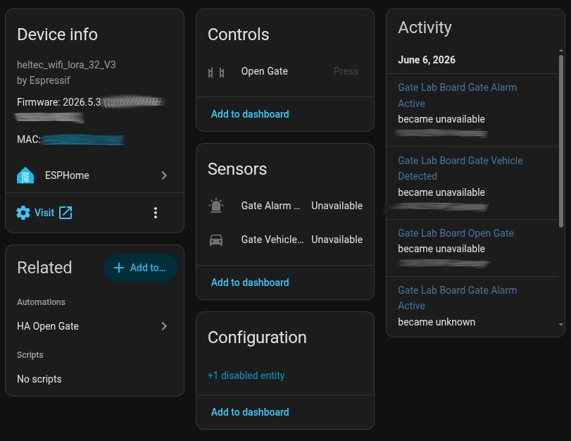
The above yaml not only interepets inbound messages and sends outbound messages, it also provides this dashboard
Installation
The installation of the lab side board was dissapointingly easy. After flashing the ESPHome firmware (one click) the device automatically came up in home assistant to be registered (one click).
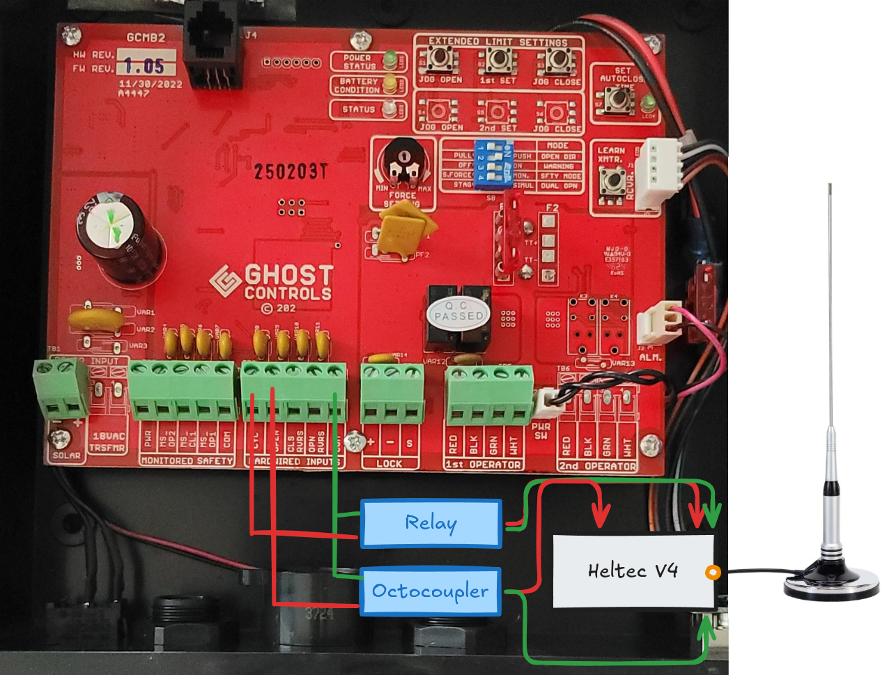
Thankfully the gate side board introduced some complications. I had to learn what VCC, OUT, IN, NO, and ON are on relays and sensors. Once again, Claude took all of the difficulties out of this, providing the pinout for each component.
- Octocoupler Installation: I skipped the alarm octocoupler for now, and decided to focus solely on the vehicle sensor. Since there is normally 12v flowing through the circuit is open, and I need to know when it is closed. With this I wired into the VCC, GPIO 6, and GND pins.
- Relay Installation: This was wired into the CYC port on the control board, meant for a push-button to open the gate. So the NO port went to the CYC port, and the COM went to the COM port. On the board side GND went to a GND pin, and VCC went to GPIO 4.
It is at this point that I messed up. I believed that the battery terminal on the Heltec V4 would accept a 12V power supply. Not a concious thought, a miss in my knowledge. This meant that when I wired in the power cables to the power supply, and plugged it into the board it immediately popped, smoked, and died. It was at this point that I learned what a “buck converter” does, and proceeded to order a new Heltec board and a handful of buck converters.
Note: I still do not understand why I do not need to use the IN and OUT ports on the octocoupler and relay and it still works. I might need another project to try and understand it through experimentation.
Automations
From this point Home Assistant goes above and beyond with a simple click through interface of trigger and action.”When Gate_Sensor:Vehicle is received (trigger), then Play Media to Speaker and send notification via mobile app (action)” I did have a spare USB speaker on hand, which I plugged into the Home Assistant server, and allowed it to play an audio file for the vehicle sensor event.
For right now, that is all that I need. I can integrate it further by dropping my thermostat when I get home by adding conditions “When Gate_Sensor:Vehicle && Time is after 6:00PM, then set thermostat to 75 deg” however this is not needed, but far exceeds the power and flexibility that Ghost Controls or a Dakota Alert could ever provide me.
Wrap up
I did not intend for this project to be powered by artificial intelligence, however it drastically reduced any headache I would have experienced, and since this is not mission critical code I am happy to have the project completed. For my initial foray into ESP32 devices this project proved their application and versatility, and I am far happier with this setup than I am with anything I could have purchased off the shelf. I have far greater control over my privacy, I have far greater range, and I have the joy of knowing I built it and learned something from it.
A quick list of things I would do differently.
- Not get the newest board, a Heltec V3 would far exceed what I needed, and I would not have needed to learn how to add a custom board profile. It was an easy fix, but it could have been project stopping.
- Made a voltage tolerance diagram. This would have shown me the 12v -> 5v discrepancy and saved me 3 days of waiting.
- Add in encryption on the messages. Right now they are plain text being sent. Although I am not too concerned, I believe that encryption should be the default with any tranmission.
- Studied a little bit more on the ESP ecosystem. With AI doing the heavy work I did not get the struggle I expected from this project, and therefore do not feel as though I capitalized on the full learning potential. It does give me more confidence to dig into a new project, but I don’t have one slated. This was planned and executed in under a week (all shipping times included).
If any of you have ideas on what I should change or expand on I would love to hear about it, or if you had a similar project I would love to study to see what was done differently.
Thanks!
- Gordon Bannon