· 10 min read
DIY automatic gate opener install
Quick overview of how I installed an automatic gate opener, and some issues I faced along the way
Analyzing and approaching the install
All good analysis involve math, and all good math involves triangles. Thankfully, this is eyeball math, not calculator math.
- Swing path: Is there anything in the gate’s path of travel? Are there physical stops at either the open or closed position?
- How far away will you need to go in order to be able to mount any control units? (Is it close and reasonable?)
- In the open position is there plenty of room on the interior to add in the control arm, with a 4-5in offset?
- How will power reasonable be supplied? (Solar / AC)
- Where and how can I mount the keypad?
Any questions beyond that are for learning the hard way.
Dear reader, please note that these questions were generated from learning the hard way
After you know you these variables you can shop for your automatic gate opener. In this case, we ended up with a Ghost Controls single gate DIY solar kit.
Mounting the components
In our kit there are 6 items to be mounted.
- Control Box
- Battery box
- Post-side control arm bracket
- Gate-side control arm bracket
- Solar panel
- Keypad
Control and Battery box
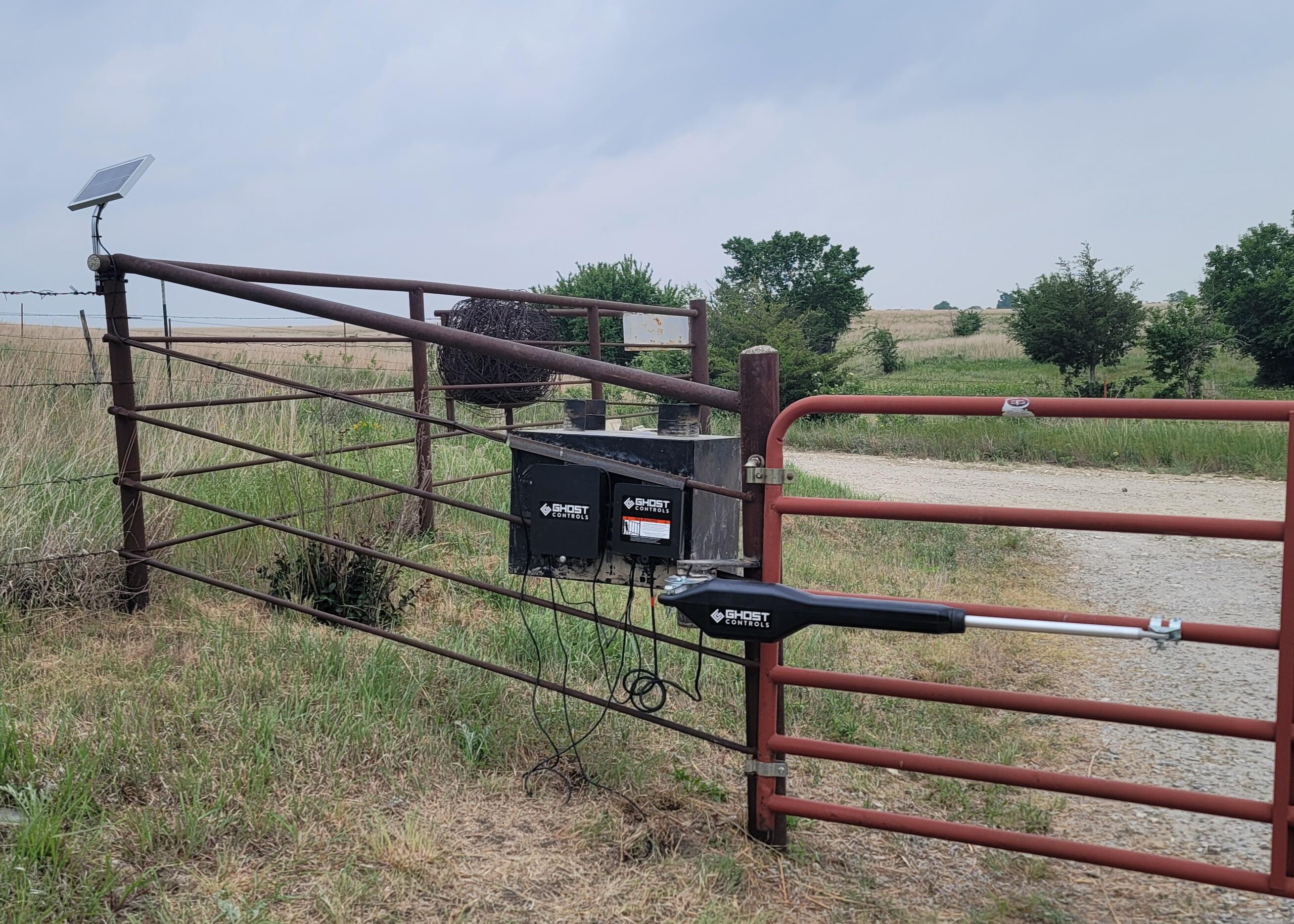
Use your discresion for procuring a flat face to secure control and battery boxes. We did this by welding flat plate as a spanner on the pipe fence. This was very secure, and allowed us to obscure the view of the controllers by putting it behind the toolbox on the exterior of the fence.
Level is secondary to secure. Ideally be both.
After the plates were welded, bolts and screws were traded out for self-tapping screws. Unlike typical applications, these boxes are mounted to metal plate, and self tapping screws are faster than bolts, and far exceed the holding requirements to keep the boxes secured.
Post-side control arm bracket
Here is where math becomes necessary. When browsing for these kits all sample applications show a gate where the hinge exist inline with the post and the gate in the closed position. This allows the mounting bracket to provide a ~4-5in offset from the gate hinge the the control arm hinge. In our application the gate hinges are 90 deg from the demonstrated configuration. This is great in most applications, as when the gate is open, the opening is the full distance between the two post, and no precious space is wasted with the hinge bolts.
After modifying the 4in bracket to follow the curve of a 4.5in post we drilled and mounted the post-side bracket directly to the same post. This did not give us enough offset, and we no longer had a triangle, instead an unfortunate trapazoid, where the gate and control arm were perfectly parallel, removing all leverage from the arm, keeping it from being able to open the gate.
The simple solution was to install another post, offset from the current post, to change the configuration of angles to match those of gates with inline hinges. In order to save some piping my dad cut a ~10in piece, and cut some saddle pieces to accompany it. This removed the need to auger and secure another post, and allowed the perfect mounting point for the post-side bracket.
Gate-side control arm bracket
This step is only fully necessary if there is a mechanical stop when the gate is in the open position.
- Fully retract the control arm
- Fully open the gate
- Align the gate-side bracket so that it lines up perfectly
- Secure the gate-side bracket
This is because you want the control arm to be able to fully close. Oftentimes the control arm will have an internal limit switch. if a portion of the arm is still extended when the gate has contact with a physical object, this limit switch is not hit, and programming open and close limits may be impossible
Solar panels
Mounting a solar panel is a straightforward endeavor. Point the solar panel at the sun between 1-3PM when the sun is at its brightest, and locate a spot that recieves sunlight at that angle the most. In many cases it can be the same post that the gate and control arm are mounted on.
For my application I decided it would be better for aesthetic purposes to mount the solar panel a little bit further out of the way to not be in the line of sight, and to help minimize risk of dust coating the panel.
Keypad
Since the keypad is wireless you have a multitude of options. You can auger a hole and install a post, you can cantilever it out off of an existing wall or post, or you could even create a mobile post with some quickrete, tire, an any pole or post available.
We chose the cantilever approach, where we calculated off of our mount point what angle would be needed to set the keypad on the high end of mailbox height (~45in) to compensate for increased pickup traffic
Wiring the components to the controller
Working on low voltage DC systems there is relatively little risk or danger, but for the safety of the electrical components ensure that the power is off, and the grounds are in place. For my DIY kit four items needed to be connected to the control panel. The control arm, solar panel, vehicle sensor, and the batteries.
The first thing I reccomend checking is how many cable ports are available on the box. If you have two like mine, group your cables in accordance to which half of the board they will be wired to. In my case the only item beign wired on the right side was the control arm, so the solar panel, battery, and vehicle sensor were fed through the left.
Every control box that I have seen has weatherproof plastic nuts/grommets that cables must be fed through. Now that your cables are grouped, find the one with the largest end pieces (Connector/plug/terminal) and feed it through the nut side first, then go down the line until all cables are through the plastic nut. We are going to repeat this step to go into the control box, but instead of pulling the cables all the way through, my suggestion is to carefully pull them through so that they can be securely wired in, with about half an inch of play. You are only trying to avoid getting too much cable in the box, and ensuring that your wiring is not taking any of the strain of keeping the cable secured.
At this point all cables should be fed into the box, through both the plastic nut and through the weatherproofing ports on the control box, and contain a half-inch of extra cable inside the control box. Now start by wiring the higher voltage items outside of the battery connections. In this case, it is the control arm.
In many cases the terminals on the board should be loosened, the wire fed through that gap, and then tightned. This keeps all strain on the screw, without transferring any to the terminal and its solderd connections.
After following the provided wiring guide, gently tug on each cable to ensure it has a secure connection, this is to avoid arcing and surges.
With that you are prepped to add power to the system. Start by shutting the switch on the control panel off, then plug in the battery terminals, check they are secure and grounded, then turn the panel on. You should hear some startup beeps, and you are ready to move on to the programming.
Programming the gate
You’re down to your last step. For me this was far more difficult than anticipated. Documentation of the programming steps and especially the troubleshooting steps was far too scarce. For the Ghost Controls keypad with a green send button, this is what I would reccomend:
Reset the keypad first.
- After connecting the batteries, disconnect one battery
- Wait 10 seconds
- Press a number on the keypad
- Wait 10 seconds
- Reconnect the battery
- Wait for three beeps
- Press the program button 3 times. (How to reset the keypad differs based upon which instruction manual or webpage you view)
Program the master code and access code. By reseting the keypad first you should be able to press the program button, enter your 4 digit pin, wait for the party light to start flashing, enter the same pin number again, wait for the party light to go off and the 1-key light to come on, and then press the transmitter up to the ghost controls label on the keypad and trigger the transmitter until the 1-key light goes off, and the yellow lock icon comes on.
- Program button
- 4 digit master pin
- Flashing party light
- 4 digit master pin again
- Solid green 1-key light
- Trigger remote transmitter until yellow lock icon illuminates
- 4 digit access code
Setting gate limits
Assuming you have correctly installed the gate-side bracket as to be able to trigger the open limit switch, setting the close limit is as simple as pressing the “jog close” button until the gate is positioned correctly. You can have the arm provide a small amount of pressure, but be aware that this may require your “safe force” tolerance level to be increased. After the gate is in the correct closed position, press the “set” button.
You are now completely set, and the gate should be fully operational!
Troubleshooting
- Ensure that the gate can fully open to hit the limit switch. Hitting an object or stop post will not allow the limits to set
- If the motor sounds strained re-evaluate your pull angle. The greater the distance between the post the back of the control arm the less effort is required to open the gate.
- When resetting the keypad ensure you click a number on the pad after the battery has been removed, otherwise I did not have luck getting it to reset.
- If the gate opens up a few degrees after shutting it is due to the force exceeding the safe-force limit. On longer gates sometimes this means that it hit the stop post and bounced back, which caused it to exceed, or it could be that you are putting too much pressure on the gate in the closed position. You can either back off the pressure slightly and re-set the limit, or with a small flat head screwdriver increase the safe-force dial.
- If anything else is strange, ensure that the gate is properly hung and swings freely.
Closing notes
Although I hope this helps someone else, this guide also serves as part of my documentation. If everything had gone smoothly I believe this job could be performed in a matter of a couple of hours. Instead I had to re-hang the gate to open properly, install our own mounting panels, hand dig the trench for the vehicle sensor, weld our own saddle to mount the control arm to, suffer from not understanding that the open limit switch would not be engauged when the gate hit an object that overrode its safe-force, and struggled through properly setting the master pin on the keypad controler from wrong and mismatched documentation. Should I need to do this again, I have a much better checklist of what to understand before ever picking up a box.
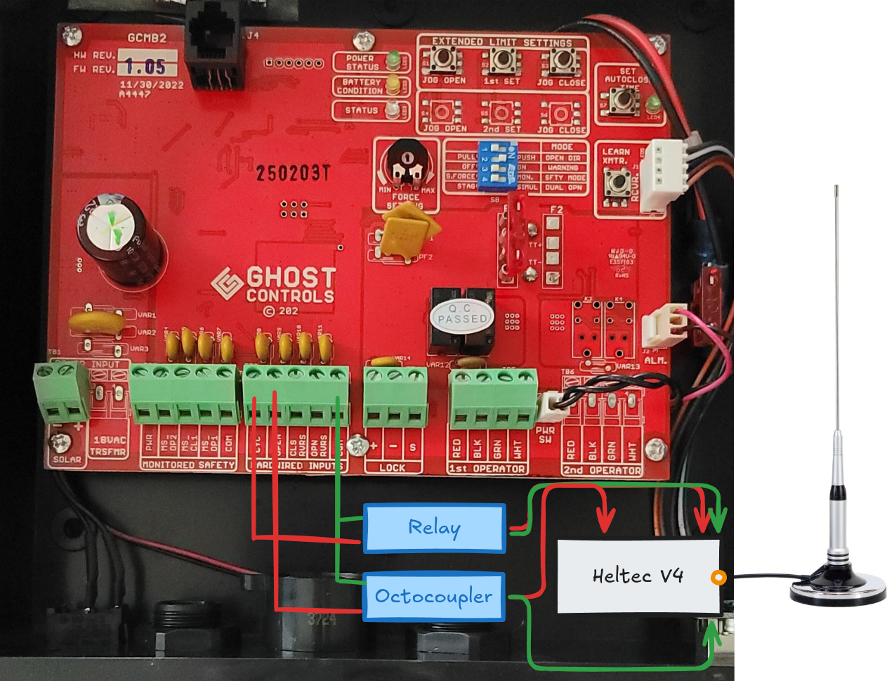
I learned a lot, troubleshooted even more, and eventually I understood it. I then took it to the next level with an ESP32 board with a long range (LoRa) antenna to allow it to be controlled from my home, which is far too far away for any type of wifi or bluetooth connection. You can read about how I integrated it into Home Assistant here